
yet another abs + brake light thread


Thread Starter
|
Member
Joined: Sep 2011
Posts: 40
Thanks. Have not yet checked the ABS pump on my Silverado. Also have not yet called modulemasters.com
The ABS module is still mounted on the truck rail.
I did check out the four T20 torx screws that mount the electrical module onto the hydraulic module. One T20 loosened up ok. Another requires a long T20 bit which i do not have yet. Another head is fairly corroded and will probably require grinding the head to get the EBCM off. And the fourth T20 is a lost cause to corrosion and will also require grinding. Once the EBCM is off, i imagine the ground off heads will leave studs, and a pair of vize grips can back em out. I can't see the heads directly, but I managed some pictures of the screw heads, so that is ho I know.
here is a close up of the fourth T20 screw head:
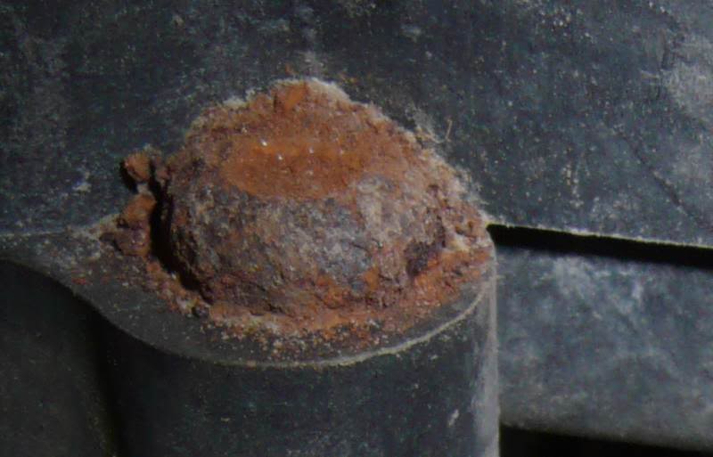
So, it looks like i'll need to pull the entire unit in order to remove the EBCM from the hydraulics. I hate to have to open up the hydraulics just to remove an electrical component.
The ABS module is still mounted on the truck rail.
I did check out the four T20 torx screws that mount the electrical module onto the hydraulic module. One T20 loosened up ok. Another requires a long T20 bit which i do not have yet. Another head is fairly corroded and will probably require grinding the head to get the EBCM off. And the fourth T20 is a lost cause to corrosion and will also require grinding. Once the EBCM is off, i imagine the ground off heads will leave studs, and a pair of vize grips can back em out. I can't see the heads directly, but I managed some pictures of the screw heads, so that is ho I know.
here is a close up of the fourth T20 screw head:
So, it looks like i'll need to pull the entire unit in order to remove the EBCM from the hydraulics. I hate to have to open up the hydraulics just to remove an electrical component.
Last edited by silv99; Sep 15, 2011 at 05:43 PM.
Thread Starter
|
Member
Joined: Sep 2011
Posts: 40
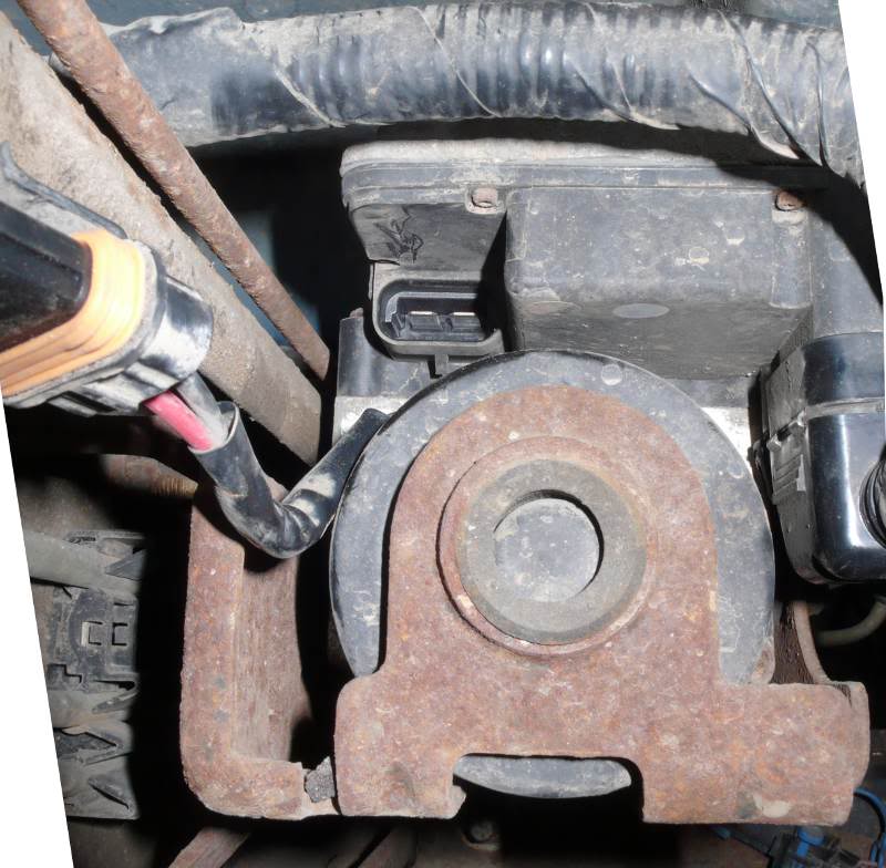
More inspection: There are 3 electrical sockets on the EBCM (Kelsey Hayes 325). One has eleven pins, the other two have 2 spades each, both red/black leads. The 2-spade socket next to the 11-connector is feed by the large wiring harness. The other 2-spade is tucked up on top of the unit. It is horizontal and the leads feed into the hydraulic/pump unit.
With the ignition off, the 2-spade near the 11-pin has 12.12 volts across the female terminals coming from the wiring harness. With the ignition off, the horizontal 2-spade has 11.09 volts across the spades in the socket.
The latter does not seem right to me. Shouldn't it be zero when the ignition is off?
Last edited by silv99; Sep 15, 2011 at 05:39 PM.

Junior Member
Joined: Sep 2009
Posts: 61
From: FL
Too bad about the rusted screw heads. Sounds like good old Yankee salt! (I lived in NY most of my life.  ) If you read the KH325 Removal Instructions on the M-master site ( ModuleMaster | Kelsey Hayes 325 Connector Removal ), they offer at least the possibility of getting the heads ground off without taking the hydraulics apart...don't know if it would really be possible or not. Of course, getting the old fluid flushed out would be good, but I'd rather tackle that as a second project.
The two-pin connectors are for the modulator pump, I think. I do not know why they are hot with the key off. Seems like that would make the pump run, unless the ~12V is just sitting there waiting for a ground to get applied. Find the connector that is going to the pump and see if you can get the pump started.
Gerald
) If you read the KH325 Removal Instructions on the M-master site ( ModuleMaster | Kelsey Hayes 325 Connector Removal ), they offer at least the possibility of getting the heads ground off without taking the hydraulics apart...don't know if it would really be possible or not. Of course, getting the old fluid flushed out would be good, but I'd rather tackle that as a second project.The two-pin connectors are for the modulator pump, I think. I do not know why they are hot with the key off.
Seems like that would make the pump run, unless the ~12V is just sitting there waiting for a ground to get applied. Find the connector that is going to the pump and see if you can get the pump started.Gerald
Thread Starter
|
Member
Joined: Sep 2011
Posts: 40
hmmm, the only wires going into the hydraulic unit or pump are the leads that attach to the horizontal 2-spade socket on the EBCM. That socket has 11.09 volts when the ignition is off and key is out. Presuming these wires power the pump, and presuming that 11 volts is sufficient to operate the pump, my guess is that the pump is dead. I suppose i could try feeding 12 volts from the battery to those wires that go into the hydraulic/pump unit.
if the pump motor is dead, can it be rebuilt or replaced?
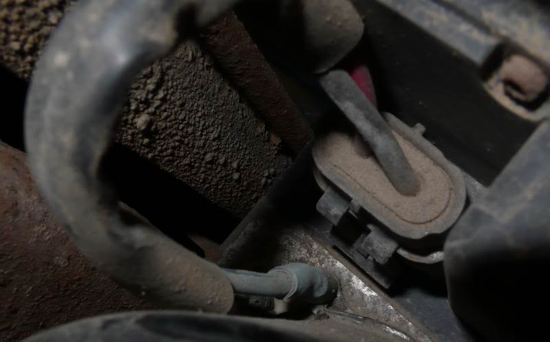
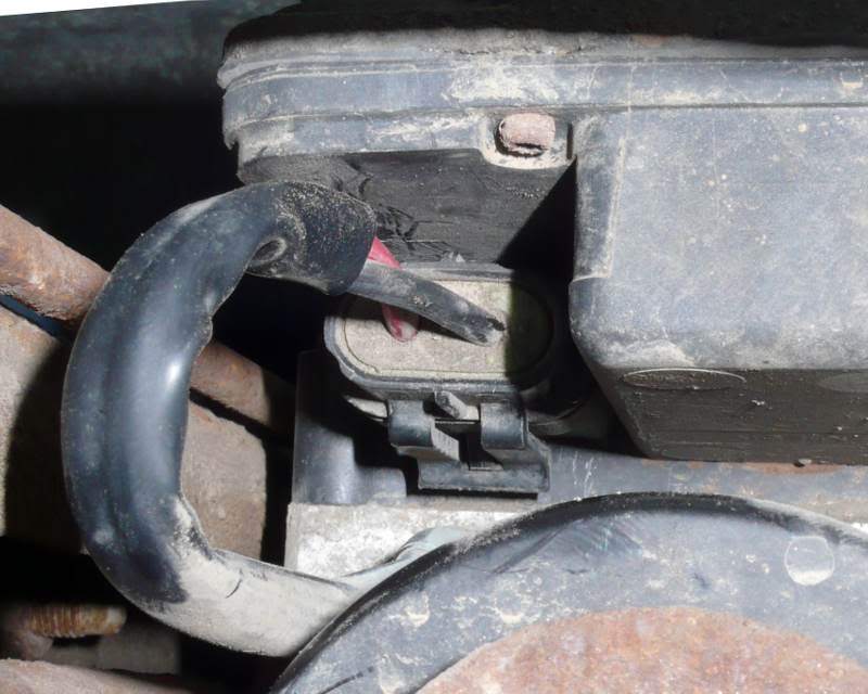
Here is the rear end of the ABS assembly, showing the 2-spade horizontal socket in the EBCM. The wires feed into the hydraulic module as shown. These spades had 11.09 volts across them.
if the pump motor is dead, can it be rebuilt or replaced?
Here is the rear end of the ABS assembly, showing the 2-spade horizontal socket in the EBCM. The wires feed into the hydraulic module as shown. These spades had 11.09 volts across them.
Last edited by silv99; Sep 15, 2011 at 05:43 PM.
Thread Starter
|
Member
Joined: Sep 2011
Posts: 40
if the pump is shot, this seems to be the entire hydraulic assembly for $112 new, shipped !
ACDelco 19149234 Brake Pressure Module Valve Assembly
ACDelco 19149234 Brake Pressure Module Valve Assembly
Junior Member
Joined: Sep 2009
Posts: 61
From: FL
I'm a little surprised that you seem to have two two-wire connectors on your EBCM module. Anyway, if the female end of the horizontal plug is what is feeding the pump and if you meter resistance across those pins, you should read the motor windings; if you read "open", the motor isn't going to be running if you apply voltage!
On mine, I fed battery 12V and battery ground to the pump pins and the pump started as it should (but that was on a 2002 Buick with a Delphi EBCM).
$112 for a new BPMV unit does not sound too bad, but you won't know if you need more until you get the thing installed.")
I would be wondering if it is worth fixing...but the experience is worth something, if you enjoy doing it. Good Luck!!
Gerald
On mine, I fed battery 12V and battery ground to the pump pins and the pump started as it should (but that was on a 2002 Buick with a Delphi EBCM).
$112 for a new BPMV unit does not sound too bad, but you won't know if you need more until you get the thing installed.
I would be wondering if it is worth fixing...but the experience is worth something, if you enjoy doing it. Good Luck!!
Gerald
Thread Starter
|
Member
Joined: Sep 2011
Posts: 40
in my original version of this post, i did not have a wiring diagram
and used C3 to refer to C2 on the Mitchell schematic, and C2 to refer
to C1 on the schematic. i've edited this post so that it uses Mitchell's
nomenclature.
more inspection today:
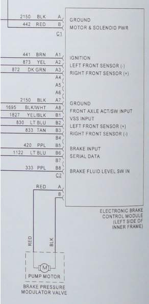
C1 is the vertical 2-spade connector that is feed by the wiring harness, and is right next to the vertical 11-pin connector AB.
C2 is the 2-spade horizontal connector feeds the pump motor.
Both have red and black leads.
All the following was done with the ignition off, key out.
I'm still reading 12 volts across the female terminals at C1.
when C1 is plugged into the EBCM, i'm still reading 11 volts across the 2 spades on C2.
when C1 is unplugged, i get zero volts across C2
between the red spade at C1 and the red spade at C2, there is near
zero resistance with the multimeter range dial at 200 Ohms.
the resistance between the black spade at C1 and the black spade
at C2 is 96.7K (multi meter dial is at 200K Ohms). My guess is that,
in essence, 96.7K ohms is the resistance across the pump motor relay
in the EBCM. This was quite awkward to measure.
between the red spades, there is near zero resistance with the
multimeter range dial at 200 Ohms.
there is near zero resistance across the female terminals
at C2, that is, zero resistance across the pump motor.
A large spark flew and the pump/motor made some very noticeable
noise when i jumped from C1 to C2 using two lengths of 12ga single
conductor. the noise was definitely not the smooth hum of an electric
motor. It probably was the sound of the pump not the pump motor.
and used C3 to refer to C2 on the Mitchell schematic, and C2 to refer
to C1 on the schematic. i've edited this post so that it uses Mitchell's
nomenclature.
more inspection today:
C1 is the vertical 2-spade connector that is feed by the wiring harness, and is right next to the vertical 11-pin connector AB.
C2 is the 2-spade horizontal connector feeds the pump motor.
Both have red and black leads.
All the following was done with the ignition off, key out.
I'm still reading 12 volts across the female terminals at C1.
when C1 is plugged into the EBCM, i'm still reading 11 volts across the 2 spades on C2.
when C1 is unplugged, i get zero volts across C2
between the red spade at C1 and the red spade at C2, there is near
zero resistance with the multimeter range dial at 200 Ohms.
the resistance between the black spade at C1 and the black spade
at C2 is 96.7K (multi meter dial is at 200K Ohms). My guess is that,
in essence, 96.7K ohms is the resistance across the pump motor relay
in the EBCM. This was quite awkward to measure.
between the red spades, there is near zero resistance with the
multimeter range dial at 200 Ohms.
there is near zero resistance across the female terminals
at C2, that is, zero resistance across the pump motor.
A large spark flew and the pump/motor made some very noticeable
noise when i jumped from C1 to C2 using two lengths of 12ga single
conductor. the noise was definitely not the smooth hum of an electric
motor. It probably was the sound of the pump not the pump motor.
Last edited by silv99; Sep 15, 2011 at 05:41 PM.
Junior Member
Joined: Sep 2009
Posts: 61
From: FL
Silv99, you need a wiring diagram. My GUESS is that when you applied C1 voltage to the female C2 pins you really did activate the motor.
As far as the resistance readings go, there are too many unknowns within the EBCM. It does not make sense that they are feeding 12V directly to the C2 red pin and it does not make sense that you would be reading a high resistance between the C1/C2 black pins, but without a wiring diagram...
Maybe someone on here with access to Alldata or with better knowledge can help. I think I would pay a visit to my local Chevy service dept. and give them a chance to be a hero by sharing a copy of the EBCM/BPMV wiring. When I was working on mine, Modulemaster helped some: even though I had established the correct pins to power the pump motor I was unsure of the correct polarity...they confirmed that I could test it without regard to the polarity. Maybe they can give you some guidance here.
Gerald
Last edited by glterpening; Sep 15, 2011 at 06:05 PM.
Thread Starter
|
Member
Joined: Sep 2011
Posts: 40
Thanks Gerald. BTW I edited my post from yesterday evening so that my nomenclature matches Mitchells. What i had been calling C2 is now C1, and C3 is now C2. Sorry for the hassle. You might want to edit your post so that it reads correctly too.
Looks like i need a schematic for the EBCM internals, which I could not find this morning in Mitchells at the library.
Anyone have a schematic for the Kelsey Hayes 325? or know I can get one?
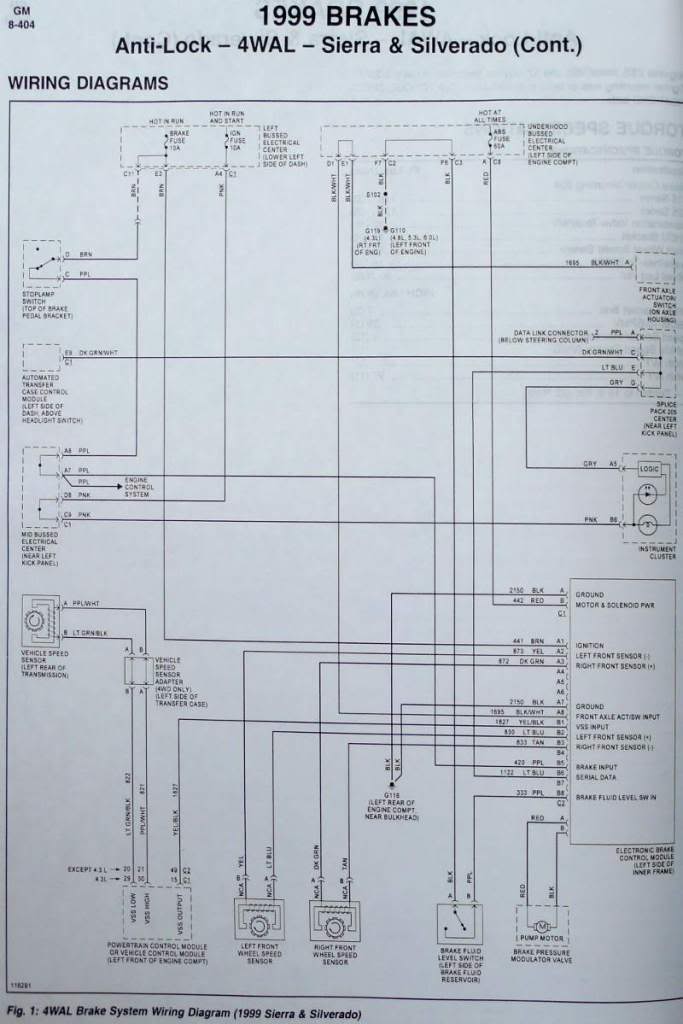
Here is the ABS schematic for 1999 silverados:
Looks like i need a schematic for the EBCM internals, which I could not find this morning in Mitchells at the library.
Anyone have a schematic for the Kelsey Hayes 325? or know I can get one?
Here is the ABS schematic for 1999 silverados:
Last edited by silv99; Sep 15, 2011 at 05:43 PM.
Thread Starter
|
Member
Joined: Sep 2011
Posts: 40
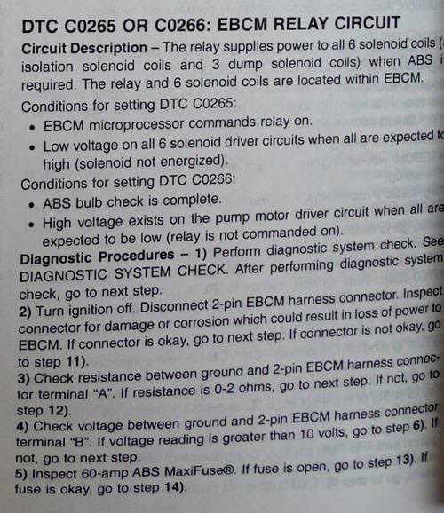
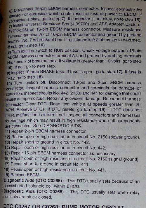
wow, that Mitchells is something else! first time using it. Since starting to work on this problem a week or two ago, the only code that has been storing is C0265.
Last edited by silv99; Sep 15, 2011 at 05:06 PM.